

 Frame build jig - CAD
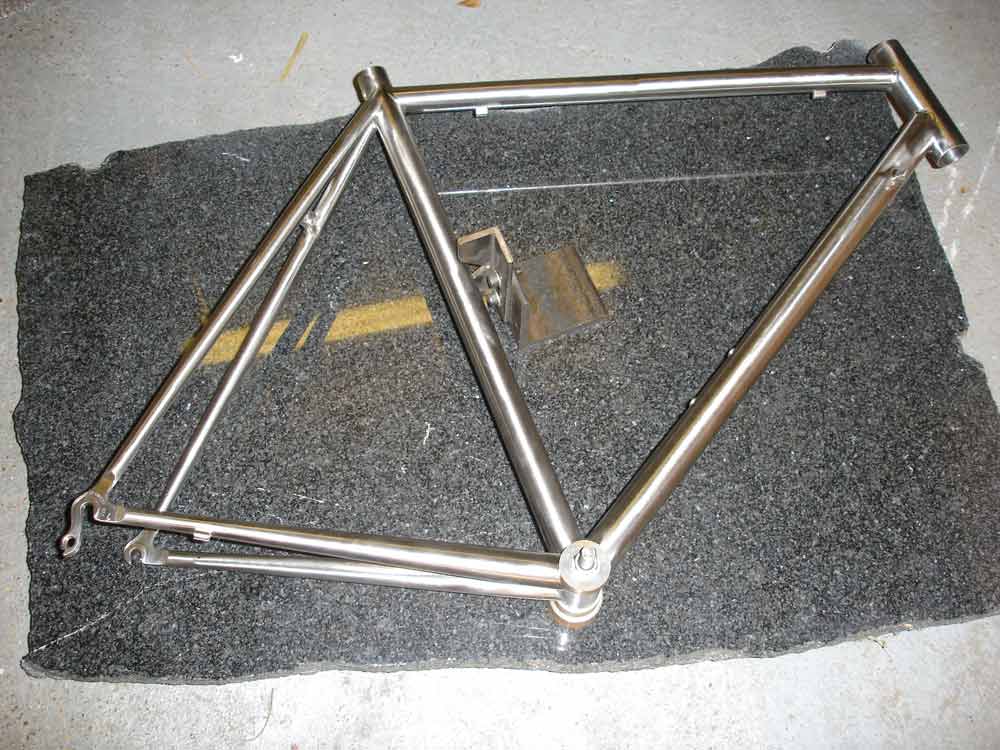
Measuring jig
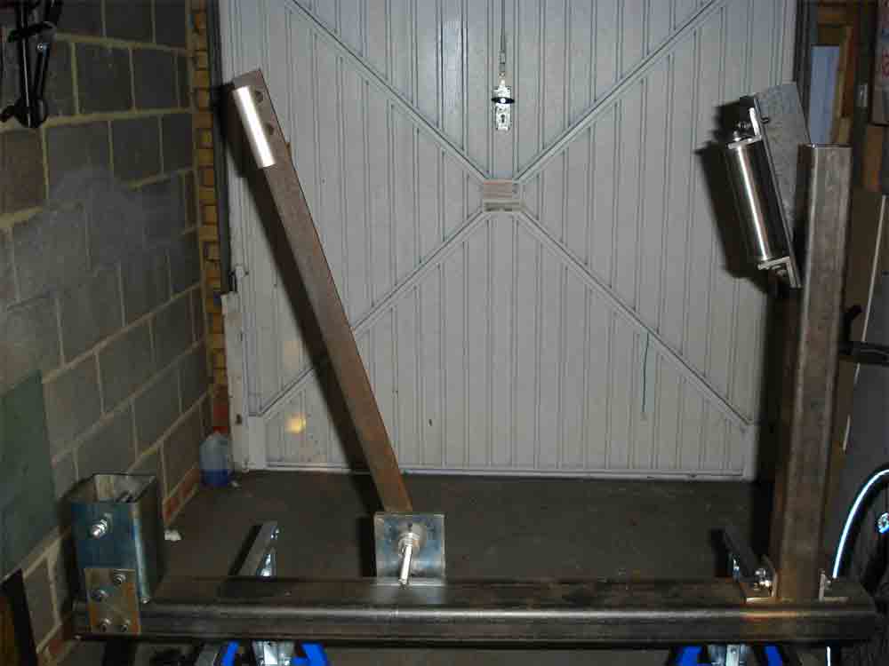
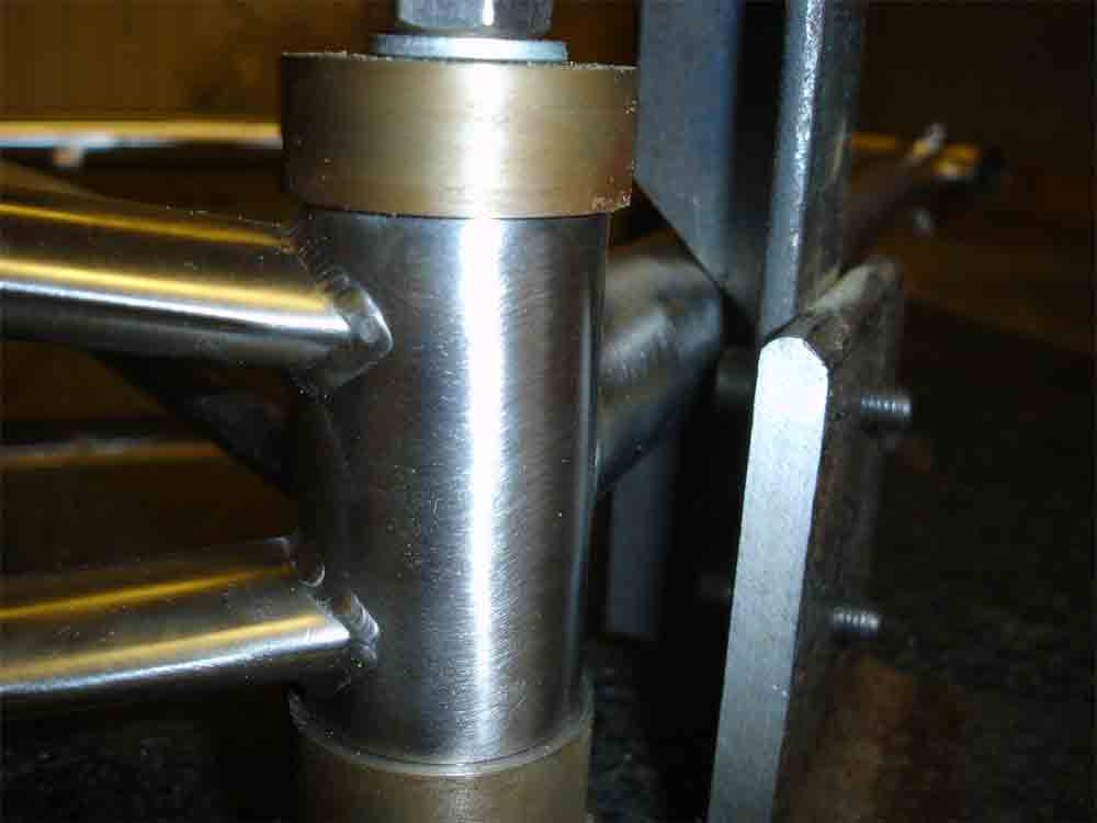
The basis for the measuring jig is a slab of polished granite from a local supplier who was was happy to let one of his rejects go to a good cause (again, for free). Granite is used because it is hard, heavy and very flat which makes it an ideal base for taking accurate measurements. The measuring jig holds the frame at the bottom bracket shell, and then all other points are measured from the granite base using my floating measuring device. In fact the measuring does not actually provide a physical dimension, it is only to check that the frame is laterally straight (side to side), and that the dropouts are properly centred.
The floating measuring device (can't think of a better name) is based on a design I saw elsewhere, but cannot remember where. This device has a flat base to allow it to slide on the granite, and a V shaped guide whose height can be adjusted to suit the tube lateral position (height from the granite). The device is aligned with a tube close to the bottom bracket to establish the correct height, and then moved around the tubes to check that the height of the tubes does not vary at the frame extremities. The device incorporates a feature which checks the spacing and alignment and lateral position of the rear dropouts.
Because the welding bit of the project was completed by someone else, who used a different build jig (same geometry, but different method of holding the tubes), the measuring jig gave some odd results to start with. It appeared as if the entire frame was leaning to the left, but after thinking about it I realised that Kevin had not used the bottom bracket shell as his datum, as I was doing. I then did some double checking and confirmed that the dropouts, seat tube and head tube were all perfectly aligned, and the bottom bracket shell was only very slightly (0.5°) out, which is not a problem.

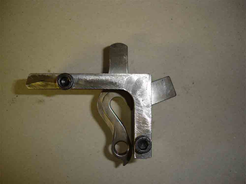
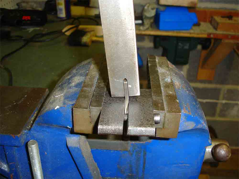
Bending the dropouts
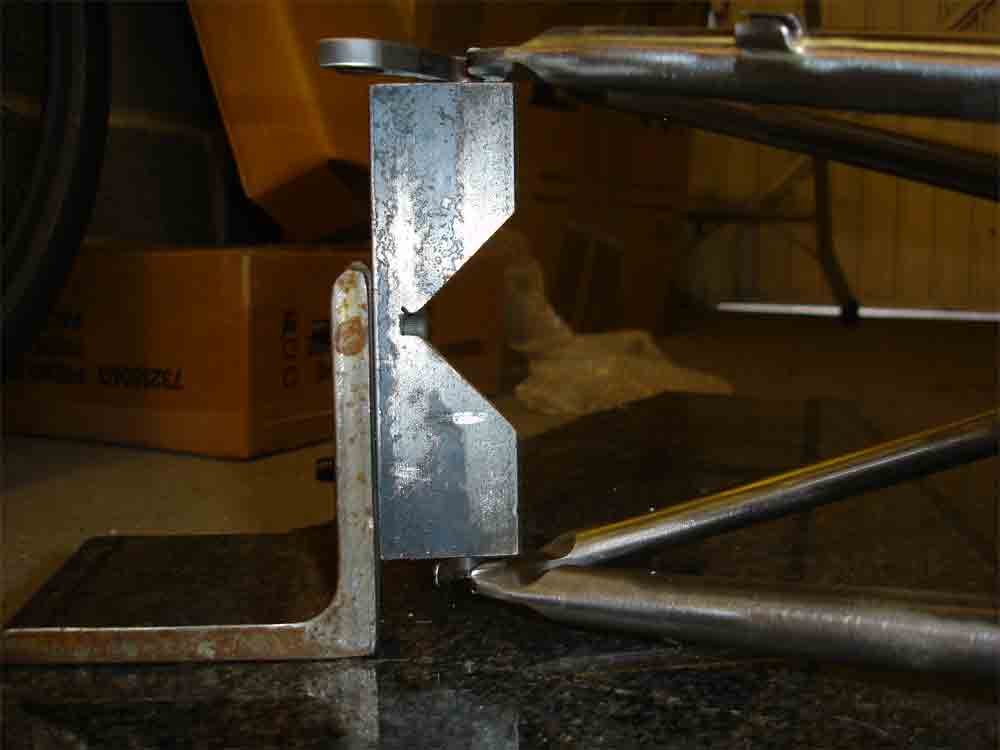
The dropouts as purchased from Reynolds were flat, and needed to be bent to suit the frame geometry. Because of the strength of the dropouts, they were not easy to bend, so I made a jig that allowed me to hold them rigidly in the vise while I pushed on the lever. I made the jig from two short lengths of angle which clamped around the dropouts while the whole lot is held in the vise.
By using the jig I was able to control exactly the position of the bend along the tab, and to some extent the bend radius. The lever was a solid steel bar with a slot cut to take the dropout tab. As with the other items featured here, all materials were sourced from a local skip.